Connecting to the Helium Wireless Network via LORA

image

DATA ONLY HELIUM HOTSPOT

ORGANIZATION for Floating Pods (H2P)

image
image
  • Webhook Key: JTDsPoPE21LGIctHJ4a9PH6Rik_r0t-k

HELIUM COVERAGE

image
image
image
image
image

DEVELOPMENT

WIO-E5 mini

REMARK: I have also notes in my “resources” database in my lab about the E5-mini

image
image

image

1) Alvaro’s module (I added to another organization, but I will add to the same than Antonio):

>> AT+ID (baud 9600):

+AT: OK

+ID: DevAddr, 32:30:76:40

+ID: DevEui, 2C:F7:F1:20:32:30:76:40 —> 2CF7F12032307640

+ID: AppEui, 80:00:00:00:00:00:00:06 —> 8000000000000006

NOTE: AppKey automatically generated by Helium Console: AE84127AE6CE5F436E17C2F897782EE1

image

2) Antonio Gordillo’s module:

Using Lora-E5 mini:

+AT: OK

+ID: DevAddr, 32:30:63:DD

+ID: DevEui, 2C:F7:F1:20:32:30:63:DD

+ID: AppEui, 80:00:00:00:00:00:00:06

2B7E151628AED2A6ABF7158809CF4F3C

2) Lora-E5 Dev Board:

2)Antonio: Lora-E5 Dev Board:

+ID: DevAddr, 42:00:77:D4

+ID: DevEui, 2C:F7:F1:20:42:00:77:D4 —> 2CF7F120420077D4

+ID: AppEui, 80:00:00:00:00:00:00:06 —> 8000000000000006

APPKEY (from helium console): CFD0DB671F6011111022AE8C81FABF69

All modules signed in Helium Network:

image

INSTALLiNG the HELIuM miner

image

CODE for sending data to helium

CODE:
/**
   @file Environment_Monitoring.ino
   @author rakwireless.com
   @brief This sketch demonstrate how to get environment data from BME680
      and send the data to lora gateway.
   @version 0.1
   @date 2020-07-28
   @copyright Copyright (c) 2020
**/

#include <Arduino.h>
#include <LoRaWan-RAK4630.h> // Click to install library: http://librarymanager/ALL#SX126x-Arduino
#include <SPI.h>

#include <Wire.h>
#include <Adafruit_Sensor.h>
#include <Adafruit_BME680.h> // Click to install library: http://librarymanager/All#Adafruit_BME680
#include <U8g2lib.h>		   // Click to install library: http://librarymanager/ALL#u8g2

U8G2_SSD1306_128X64_NONAME_F_HW_I2C u8g2(U8G2_R0);
Adafruit_BME680 bme;

// RAK4630 supply two LED
#ifndef LED_BUILTIN
#define LED_BUILTIN 35
#endif

#ifndef LED_BUILTIN2
#define LED_BUILTIN2 36
#endif

bool doOTAA = true;   // OTAA is used by default.
#define SCHED_MAX_EVENT_DATA_SIZE APP_TIMER_SCHED_EVENT_DATA_SIZE /**< Maximum size of scheduler events. */
#define SCHED_QUEUE_SIZE 60										  /**< Maximum number of events in the scheduler queue. */
#define LORAWAN_DATERATE DR_3									  /*LoRaMac datarates definition, from DR_0 to DR_5*/
#define LORAWAN_TX_POWER TX_POWER_0								  /*LoRaMac tx power definition, from TX_POWER_0 to TX_POWER_15*/
#define JOINREQ_NBTRIALS 5										  /**< Number of trials for the join request. */
DeviceClass_t g_CurrentClass = CLASS_A;					/* class definition*/
LoRaMacRegion_t g_CurrentRegion = LORAMAC_REGION_EU868;    /* Region:EU868*/
lmh_confirm g_CurrentConfirm = LMH_CONFIRMED_MSG;				  /* confirm/unconfirm packet definition*/
uint8_t gAppPort = LORAWAN_APP_PORT;							  /* data port*/

/**@brief Structure containing LoRaWan parameters, needed for lmh_init()
*/
static lmh_param_t g_lora_param_init = {LORAWAN_ADR_OFF, LORAWAN_DATERATE, LORAWAN_PUBLIC_NETWORK, JOINREQ_NBTRIALS, LORAWAN_TX_POWER, LORAWAN_DUTYCYCLE_OFF};

// Foward declaration
static void lorawan_has_joined_handler(void);
void lorawan_join_fail(void);
static void lorawan_rx_handler(lmh_app_data_t *app_data);
static void lorawan_confirm_class_handler(DeviceClass_t Class);
static void send_lora_frame(void);

/**@brief Structure containing LoRaWan callback functions, needed for lmh_init()
*/
static lmh_callback_t g_lora_callbacks = {BoardGetBatteryLevel, BoardGetUniqueId, BoardGetRandomSeed,
                                        lorawan_rx_handler, lorawan_has_joined_handler, lorawan_confirm_class_handler, lorawan_join_fail
                                       };

//OTAA keys !!!! KEYS ARE MSB !!!!
uint8_t nodeDeviceEUI[8] = {0xE9, 0x3C, 0x83, 0xCF, 0xDE, 0xC5, 0xDF, 0xB5};
uint8_t nodeAppEUI[8] = {0x7B, 0x84, 0x17, 0x9A, 0xC2, 0x4B, 0x0B, 0x34};
uint8_t nodeAppKey[16] = {0xD0, 0x5D, 0xAE, 0xA1, 0xC3, 0xBC, 0xD9, 0xD3, 0x62, 0x67, 0xB3, 0x5F, 0x06, 0x1A, 0x92, 0x34};

// ABP keys
uint32_t nodeDevAddr = 0x260116F8;
uint8_t nodeNwsKey[16] = {0x7E, 0xAC, 0xE2, 0x55, 0xB8, 0xA5, 0xE2, 0x69, 0x91, 0x51, 0x96, 0x06, 0x47, 0x56, 0x9D, 0x23};
uint8_t nodeAppsKey[16] = {0xFB, 0xAC, 0xB6, 0x47, 0xF3, 0x58, 0x45, 0xC7, 0x50, 0x7D, 0xBF, 0x16, 0x8B, 0xA8, 0xC1, 0x7C};

// Private defination
#define LORAWAN_APP_DATA_BUFF_SIZE 64										  /**< buffer size of the data to be transmitted. */
#define LORAWAN_APP_INTERVAL 20000											  /**< Defines for user timer, the application data transmission interval. 20s, value in [ms]. */
static uint8_t m_lora_app_data_buffer[LORAWAN_APP_DATA_BUFF_SIZE];			  //< Lora user application data buffer.
static lmh_app_data_t m_lora_app_data = {m_lora_app_data_buffer, 0, 0, 0, 0}; //< Lora user application data structure.

TimerEvent_t appTimer;
static uint32_t timers_init(void);
static uint32_t count = 0;
static uint32_t count_fail = 0;

void setup()
{
  // Initialize the built in LED
  pinMode(LED_BUILTIN, OUTPUT);
  digitalWrite(LED_BUILTIN, LOW);

  // Initialize Serial for debug output
  Serial.begin(115200);

  time_t serial_timeout = millis();
  // On nRF52840 the USB serial is not available immediately
  while (!Serial)
  {
    if ((millis() - serial_timeout) < 5000)
    {
      delay(100);
      digitalWrite(LED_BUILTIN, !digitalRead(LED_BUILTIN));
    }
    else
    {
      break;
    }
  }

  Serial.println("=====================================");
  Serial.println("Welcome to RAK4630 LoRaWan!!!");
  if (doOTAA)
  {
  Serial.println("Type: OTAA");
  }
  else
  {
    Serial.println("Type: ABP");
  }

  switch (g_CurrentRegion)
  {
    case LORAMAC_REGION_AS923:
  Serial.println("Region: AS923");
      break;
    case LORAMAC_REGION_AU915:
  Serial.println("Region: AU915");
      break;
    case LORAMAC_REGION_CN470:
  Serial.println("Region: CN470");
      break;
    case LORAMAC_REGION_EU433:
  Serial.println("Region: EU433");
      break;
    case LORAMAC_REGION_IN865:
  Serial.println("Region: IN865");
      break;
    case LORAMAC_REGION_EU868:
  Serial.println("Region: EU868");
      break;
    case LORAMAC_REGION_KR920:
  Serial.println("Region: KR920");
      break;
    case LORAMAC_REGION_US915:
  Serial.println("Region: US915");
      break;
  }
  Serial.println("=====================================");

  // Initialize LoRa chip.
  lora_rak4630_init();

  /* bme680 init */
  init_bme680();

  u8g2.begin();

  //creat a user timer to send data to server period
  uint32_t err_code;

  err_code = timers_init();
  if (err_code != 0)
  {
    Serial.printf("timers_init failed - %d\n", err_code);
    return;
  }

  // Setup the EUIs and Keys
  if (doOTAA)
  {
  lmh_setDevEui(nodeDeviceEUI);
  lmh_setAppEui(nodeAppEUI);
  lmh_setAppKey(nodeAppKey);
  }
  else
  {
    lmh_setNwkSKey(nodeNwsKey);
    lmh_setAppSKey(nodeAppsKey);
    lmh_setDevAddr(nodeDevAddr);
  }

  // Initialize LoRaWan
  err_code = lmh_init(&g_lora_callbacks, g_lora_param_init, doOTAA, g_CurrentClass, g_CurrentRegion);
  if (err_code != 0)
  {
    Serial.printf("lmh_init failed - %d\n", err_code);
    return;
  }

  // Start Join procedure
  u8g2.clearBuffer();					// clear the internal memory
  u8g2.setFont(u8g2_font_ncenB10_tr); // choose a suitable font

  u8g2.drawStr(20, 39, "Joining ...");
  u8g2.sendBuffer(); // transfer internal memory to the display
  
  lmh_join();
}

void loop()
{
  // Put your application tasks here, like reading of sensors,
  // Controlling actuators and/or other functions. 
}

/**@brief LoRa function for failed Join event
*/
void lorawan_join_fail(void)
{
  Serial.println("OTAA join failed!");
}

/**@brief LoRa function for handling HasJoined event.
*/
void lorawan_has_joined_handler(void)
{
  Serial.println("OTAA Mode, Network Joined!");
  u8g2.clearBuffer();					// clear the internal memory
  u8g2.setFont(u8g2_font_ncenB10_tr); // choose a suitable font

  u8g2.drawStr(20, 39, "Joined");
  u8g2.sendBuffer(); // transfer internal memory to the display
  //delay(2000);

  lmh_error_status ret = lmh_class_request(g_CurrentClass);
  if (ret == LMH_SUCCESS)
  {
    delay(1000);
    TimerSetValue(&appTimer, LORAWAN_APP_INTERVAL);
    TimerStart(&appTimer);
  }
}

/**@brief Function for handling LoRaWan received data from Gateway
   @param[in] app_data  Pointer to rx data
*/
void lorawan_rx_handler(lmh_app_data_t *app_data)
{
  Serial.printf("LoRa Packet received on port %d, size:%d, rssi:%d, snr:%d, data:%s\n",
                app_data->port, app_data->buffsize, app_data->rssi, app_data->snr, app_data->buffer);
}

void lorawan_confirm_class_handler(DeviceClass_t Class)
{
  Serial.printf("switch to class %c done\n", "ABC"[Class]);
  // Informs the server that switch has occurred ASAP
  m_lora_app_data.buffsize = 0;
  m_lora_app_data.port = gAppPort;
  lmh_send(&m_lora_app_data, g_CurrentConfirm);
}

void send_lora_frame(void)
{
  if (lmh_join_status_get() != LMH_SET)
  {
    //Not joined, try again later
    return;
  }
  if (!bme.performReading()) {
    return;
  }
  bme680_get();

  lmh_error_status error = lmh_send(&m_lora_app_data, g_CurrentConfirm);
  if (error == LMH_SUCCESS)
  {
    count++;
    Serial.printf("lmh_send ok count %d\n", count);
  }
  else
  {
    count_fail++;
    Serial.printf("lmh_send fail count %d\n", count_fail);
  }
}

/**@brief Function for handling user timerout event.
*/
void tx_lora_periodic_handler(void)
{
  TimerSetValue(&appTimer, LORAWAN_APP_INTERVAL);
  TimerStart(&appTimer);
  Serial.println("Sending frame now...");
  send_lora_frame();
}

/**@brief Function for the Timer initialization.
   @details Initializes the timer module. This creates and starts application timers.
*/
uint32_t timers_init(void)
{
  TimerInit(&appTimer, tx_lora_periodic_handler);
  return 0;
}

void init_bme680(void)
{
  Wire.begin();

  if (!bme.begin(0x76)) {
    Serial.println("Could not find a valid BME680 sensor, check wiring!");
    return;
  }

  // Set up oversampling and filter initialization
  bme.setTemperatureOversampling(BME680_OS_8X);
  bme.setHumidityOversampling(BME680_OS_2X);
  bme.setPressureOversampling(BME680_OS_4X);
  bme.setIIRFilterSize(BME680_FILTER_SIZE_3);
  bme.setGasHeater(320, 150); // 320*C for 150 ms
}

String data = "";

void bme680_get()
{
  char oled_data[32] = {0};
  Serial.print("result: ");
  uint32_t i = 0;
  memset(m_lora_app_data.buffer, 0, LORAWAN_APP_DATA_BUFF_SIZE);
  m_lora_app_data.port = gAppPort;

  double temp = bme.temperature;
  double pres = bme.pressure / 100.0;
  double hum = bme.humidity;
  uint32_t gas = bme.gas_resistance;

  data = "Tem:" + String(temp) + "C " + "Hum:" + String(hum) + "% " + "Pres:" + String(pres) + "KPa " + "Gas:" + String(gas) + "Ohms";
  Serial.println(data);

  // display bme680 sensor data on OLED
  u8g2.clearBuffer();					// clear the internal memory
  u8g2.setFont(u8g2_font_ncenB10_tr); // choose a suitable font

  memset(oled_data, 0, sizeof(oled_data));
  sprintf(oled_data, "T=%.2fC", temp);
  u8g2.drawStr(3, 15, oled_data);

  memset(oled_data, 0, sizeof(oled_data));
  snprintf(oled_data, 64, "RH=%.2f%%", hum);
  u8g2.drawStr(3, 30, oled_data);

  memset(oled_data, 0, sizeof(oled_data));
  sprintf(oled_data, "P=%.2fhPa", pres);
  u8g2.drawStr(3, 45, oled_data);

  memset(oled_data, 0, sizeof(oled_data));
  sprintf(oled_data, "G=%dOhms", gas);
  u8g2.drawStr(3, 60, oled_data);

  u8g2.sendBuffer(); // transfer internal memory to the display

  uint16_t t = temp * 100;
  uint16_t h = hum * 100;
  uint32_t pre = pres * 100;

  //result: T=28.25C, RH=50.00%, P=958.57hPa, G=100406 Ohms
  m_lora_app_data.buffer[i++] = 0x01;
  m_lora_app_data.buffer[i++] = (uint8_t)(t >> 8);
  m_lora_app_data.buffer[i++] = (uint8_t)t;
  m_lora_app_data.buffer[i++] = (uint8_t)(h >> 8);
  m_lora_app_data.buffer[i++] = (uint8_t)h;
  m_lora_app_data.buffer[i++] = (uint8_t)((pre & 0xFF000000) >> 24);
  m_lora_app_data.buffer[i++] = (uint8_t)((pre & 0x00FF0000) >> 16);
  m_lora_app_data.buffer[i++] = (uint8_t)((pre & 0x0000FF00) >> 8);
  m_lora_app_data.buffer[i++] = (uint8_t)(pre & 0x000000FF);
  m_lora_app_data.buffer[i++] = (uint8_t)((gas & 0xFF000000) >> 24);
  m_lora_app_data.buffer[i++] = (uint8_t)((gas & 0x00FF0000) >> 16);
  m_lora_app_data.buffer[i++] = (uint8_t)((gas & 0x0000FF00) >> 8);
  m_lora_app_data.buffer[i++] = (uint8_t)(gas & 0x000000FF);
  m_lora_app_data.buffsize = i;
}
DECODER function (Helium console):
function Decoder(bytes, port) {
      var decoded = {};
      decoded.temperature = (bytes[1] << 8 | (bytes[2])) / 100
      decoded.humidity = (bytes[3] << 8 | (bytes[4])) / 100
      decoded.pressure = (bytes[8] | (bytes[7] << 8) | (bytes[6] << 16) | (bytes[5] << 24)) / 100
      decoded.gas = bytes[12] | (bytes[11] << 8) | (bytes[10] << 16) | (bytes[9] << 24)
  // TODO: Transform bytes to decoded payload below
  var decodedPayload = {
    "temperature": decoded.temperature,
    "humidity": decoded.humidity,
    "pressure": decoded.pressure,
    "gas": decoded.gas
  };
  // END TODO

  return Serialize(decodedPayload)
}

Some interesting examples:

HOW TO PROGRAM the module (not use as a modem lora-series)

—> complicated!! Need SDK from STMicroelectronics
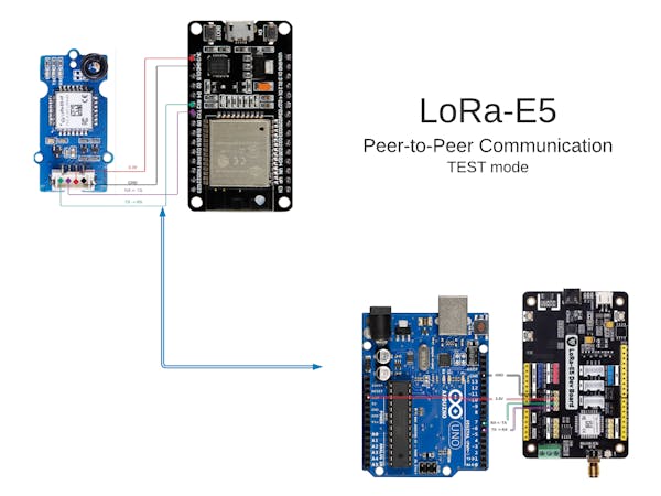
P2P with Lora

Connecting Helium to GoogleForms:

NOTE: in the future, the communication inside the pods could use CAN BUS, like in cars:

image

Using the modules as a “modem” Lora-Series

image

TUTORIAL (with Xiao)

The grove E5 need to configure what frequency plan to use based on your country . In my case, for Malaysia  we will use AS923  for the frequency plan. If you live in other countries, kindly refer to this page  to get more information about the frequency plans.

image

image

image

AS923-925 (“AS2”)

Used in Brunei, Cambodia, Hong Kong, Indonesia, Laos, Taiwan, Thailand, Vietnam

Uplink:

  1. 923.2 - SF7BW125 to SF12BW125
  2. 923.4 - SF7BW125 to SF12BW125
  3. 923.6 - SF7BW125 to SF12BW125
  4. 923.8 - SF7BW125 to SF12BW125
  5. 924.0 - SF7BW125 to SF12BW125
  6. 924.2 - SF7BW125 to SF12BW125
  7. 924.4 - SF7BW125 to SF12BW125
  8. 924.6 - SF7BW125 to SF12BW125
  9. 924.5 - SF7BW250
  10. 924.8 - FSK

Downlink:

  • Uplink channels 1-10 (RX1)
  • 923.2 - SF10BW125 (RX2)

KR920-923

Uplink:

  1. 922.1 - SF7BW125 to SF12BW125
  2. 922.3 - SF7BW125 to SF12BW125
  3. 922.5 - SF7BW125 to SF12BW125
  4. 922.7 - SF7BW125 to SF12BW125
  5. 922.9 - SF7BW125 to SF12BW125
  6. 923.1 - SF7BW125 to SF12BW125
  7. 923.3 - SF7BW125 to SF12BW125
  8. none

Downlink:

  • Uplink channels 1-7
  • 921.9 - SF12BW125 (RX2; SF12BW125 might be changed to SF9BW125)

IN865-867

Uplink:

  1. 865.0625 - SF7BW125 to SF12BW125
  2. 865.4025 - SF7BW125 to SF12BW125
  3. 865.9850 - SF7BW125 to SF12BW125

Downlink:

  • Uplink channels 1-3 (RX1)
  • 866.550 - SF10BW125 (RX2)

IPFS for IoT

An exciting and presently practical implementation of Distributed Ledger Technology is the Interplanetary File System (IPFS) (https://ipfs.io/). IPFS creates a distributed file system across independent nodes. IPFS can be used to host websites, files, and even videos.IPFS nodes store only the content they're interested in as well as an index of who is storing what. This is unlike traditional blockchains that require each node to have the entire history of transactions stored locally. IPFS may be very different from conventional blockchains, but similar in that cryptographic hashes of files save across multiple nodes in a network. The claim to fame for IPFS (https://ipfs.io/ipfs/QmNhFJjGcMPqpuYfxL62VVB9528NXqDNMFXiqN5bgFYiZ1/its-time-for-the-permanent-web.html)is the bold suggestion that the entire public web itself would better serve the world if it used IPFS rather than centralized HTTP servers. Each client node has access to the whole network of files if you know the hash address. Client nodes can decide to store the hash and in doing so becomes a host node of that data. If any nodes storing the data is disconnected, the file continues to be available through the other nodes as if nothing happened.In addition to the storage tools it exposes to application developers, IPFS also exposes a pub/sub event bus similar to MQTT. Unlike MQTT there is no centralized Broker, IPFS provides a completely decentralized and distributed Broker equivalent. This means that every subscriber interested in an event also acts collectively to Broker event syndication to other interested subscribers. Then, there is also the added benefit of built-in cryptographic security.You can use IPFS Pub/Sub today (https://ipfs.io/blog/25-pubsub/), but you'd quickly run into the reality that IPFS requires nodes to opt-in to host individual data. For this reason, larger projects built on top of IPFS provide value by bringing structure, libraries, and a "network" of interested nodes all running the same project application.One project built upon IPFS is Computes.io (https://computes.io/). The founder, Chris Matthieu (https://twitter.com/ChrisMatthieu), wrote a blog post that demoed an IoT pub/sub example using an Arduino last year - Build an IoT Supercomputer (https://blog.computes.com/building-an-iot-supercomputer-918f5b15cec0). The term supercomputer might raise your eyebrow but consider this demo where Computes demos a brute force password attack using multiple computers acting like one.[embed]https://www.youtube.com/watch?v=_csMpIEJLxo[/embed]IPFS gives us the ability to network a series of IoT devices and have them act as a shared file system, an event bus, and with Computes.io as a distributed computation platform.

Helium to IPFS:

image

INTERESTING READS